The SPAM (before it became known as the SPAM mark I) was our crowning glory. All additions to it seemed mere window dressing, the tribute due to it as our way for thanking it for working. Its elegance enraptured us and entranced our colleagues. It has touched us deeply and will remain within our hearts forever.
Before we actually set about designing and building SPAM, we decided to set up some standards so that our individual contributions could be combined into a fabulous whole. After meditating long and hard on EECS gestalt, we came up with some ideas.
For our schematics, our schematic drawing software made most of our standardization decisions for us. The built in 7400 libraries used what the data manuals call "conventional" logic symbols, as opposed to those funny looking things that the IEEE uses. Wires are drawn thin and red. Busses are drawn thick and green. Chips are identified by number, with the 74- prefix omitted in many cases. Pin numbers are included above or to the right of their respective pins. Connections between pages are shown by a symbol that looks like a milk carton turned on its side. You'll recognize it when you see it. Our signal names went by names of the format XXX_YYY, with XXX being a three-letter code associated with a block, and YYY being another 3-letter code corresponding to a signal vital to that block. For instance, CLK_FST was our fast clock while RAM_CS\ stood for the ram's chip select. Bashes ("\") stood for active-low controller outputs.
In our microcode, we used an old 6502 assembler called Big Mac, written to run on an Apple II. This makes our microcode rather strange looking, but overall fairly easy to read. We wrote macros for the various controller commands. Each macro call generates one byte, and the constant (defined on line 3) HIGH_ROM controls whether the byte is for the high or low controller EPROM. The assembler command ">>>" invokes a macro. Other assembler commands (not microcode) are LST ON/OFF, which turns assembly printout on and off, and DO/ELSE/FIN, which does conditional assembly. For the most part, you can ignore these, and concentrate on the microcode itself. In the assembler, comment lines are either blank or begin with a "*". In addition, lines may have comments at the end, separated from the code by a semicolon. This is not to be confused with the semicolon separating the branch destination from the branch instruction in a branch macro. Also, we made it a point every time we invoked the BEEP macro to include the comment BEEP! on that line. For your elucidation, assembly times averaged 15 seconds on an Apple IIGS.
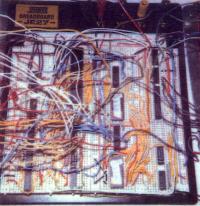
When actually putting SPAM together, we agreed on wiring standards. For our various clocks we used different shades of green. Red was power, black was ground, where such connections were deemed significant. For just providing power and ground to chips, staples were used to reduce tangle. Purple was used for the data bus. For controller outputs, blue was the color of preference, and white was used for controller outputs. Yellow and white were used for everything else. For all data and address busses, orange wire was used to identify the high bit. Thus, in the four bit wide data bus, we used 3 purple wires for the low bits, and one orange for the high. Or sometimes four purple, when we were out of orange. For wires that went in between boards, we often did not bother to color-code them, as when dismantling the project we would take them out anyhow - when reassembling, we didn't want to bother with finding wires that were not only long enough but the correct color besides. We also used the idea of "orange means high" with our EPROMs, labeling one with an orange sticker to set it apart from the other, labeled with a yellow sticker. We set aside various pieces of board for various blocks. Our one 'nice' board (the black one in the middle) we set aside for the tough parts of SPAM - the controller and address controller. I/O was apportioned one board. Later, when we began work on the Mark II, the add-ons got their own board. Each board had a separate 'power light' (an LED wired between power and ground in series with a resistor) to help detect shorts. Oh yeah, and we also decided which way on each board was going to be 'right side up' - that is, which way all the chips should face. After a while, this came to be known as 'North'.
Next: Module Descriptions