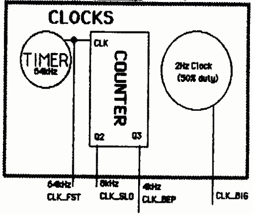
"Real Time" Clock
Bus Monitor
Address Controller Redux
New Controller I/O Info
Blinky : Everybody's Favorite Finite State Machine
We still had a problem with various operations taking place on vastly different time scales. Controller was still going fast. Analog stuff was kind of slow. Beep was a big slower. But now we needed something to keep track of whether a short amount of time had passed since a message had started playing. If it had, rewind was supposed to plunk the user at the beginning to the message he was listening to. If they pressed it earlier, they would hear the previous message. Have we mentioned how slow humans are? It takes them a long time between button presses.
What's worse, they were expected to see a light blink and be able to count the blinks. So that meant we were going to need a slow blinker.
The solution was obviously a new clock. Not shown in this diagram, it was run through a counter. For the two clock speeds. CLK_FSM controlled the Finite State Machine. CLK_BIG, 4 times slower was set up as the REWIND threshold. We could have taken care of the whole thing with just another counter. But we wanted this clock to be adjustable - we weren't that sure about how long it took people to hit a button twice. Or notice a blink.
Up until this point, we had been able to avoid looking at the data at all. The controller didn't care whether it was recording a regular voice, pure silence, or the Lost Doggie Blues as performed by Megabrooce. Now we were supposed to test for silence. Our mike rests at 7 or 8. If the mike is on, but no one is talking into it, its signal doesn't wobble much. But sometimes, after we fine tuned it, it would rest at a different level.
So we set up our Silence Catcher so it would have an adjustable rest level. We used a bank of 4 switches, one switch for each bit of data. We would add together the vox data to the number given by the switches, ignoring overflow. If the result was low (both high bits low), the output of the OR gate would be low. This was silence. Anything else was noise. We used the latch as a flag which could be set. Any noise on the line would set the latch. USR_DON would reset it.
We considered using a comparator for this, but we were looking for a middle range, so testing for < or > would have been useless. And testing for = would have been asking a lot of our mike - it still gave occasional 1-bit variations. Maybe an adder and a < comparator together would have been nice, but our or gate is basically a way to test if the output of the adder is <4. Its output was called BUS_BUZ, or sometimes BUS_MON.
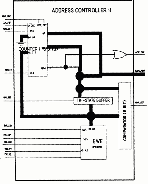
Most of the new wiring was going to go into our new Address Controller. This was to allow for variable length messages. The way we ended up implementing this was allowing the RAM address to be stored to another RAM (called EWE (pronounced "A-WAY")) Now the counters would be loaded from EWE, instead of from Current Message. Current Message instead became an input to EWE, as address selectors. Another address selector was the controller output EWE_SEL, which was used to decide whether the controller wanted to deal with the end of a message as opposed to the beginning. The EWE would store values by activating the latch connecting the counter outputs (which it would do when ADR_GT\ went low) to the EWE I/O pins, while EWE_WE\ (write enable for EWE) was low (active).
Once an address was selected and EWE_CS\ (the chip select for the EWE) went low, the counter-supplied address would be stored. The comparator was there to compare the current RAM_ADR to the stored end address of a message - when the two are equal, the end of the message has been reached. The comparator's output is the controller input ADR_EQ\. ADR_DON was changed slightly, since its old function was obsolete. It was now equal to RAM_ADR:14 OR RAM_ADR:15, that is was active if either of the two high bits was high. This was for use with setting the start and end of the Outgoing Message, which was still to be 2 seconds long.
We considered using a page-based memory-allocation & garbage-collection scheme. We would have used the EWE to keep track of a list of free pages. Whenever recording, EWE would be searched for the next free page. Each message would have its own list of pages to be played in sequence. It would have worked out very nicely if we had decided to do selective erasure, since garbage collection would already be implemented. But we decided against doing selective erase, and decided to go with the straightforward approach for testability reasons. It's pretty easy to tell if your counters are counting correctly, but it can be tough to keep track of whether they're jumping to the right places.
SPAM mark II filled up our controller inputs and outputs. New inputs were ADR_EQU (RAM_ADR = EWE output), BUS_BUZ(data bus noisy), CLK_FSM (another slow clock to synch with). New outputs were EWE_SEL (Select whether beginning or ending address of message desired from EWE), ADR_GT\ (allow present address onto EWE's pins), EWE_CS\, and EWE_WE\ (chip select and write enable for EWE).
This FSM consisted of an EPROM and a latch. The latch got CLK_FSM as a clock, with inputs from the ROM. The ROM's address was selected by MSG_MC0, MSG_MC1 (the message count), and the outputs of the latches, loading what the address had been last time. Here's Blinky's (Everybody's Favorite Finite State Machine's) hex listing:
Old Addr    0    1    2    3    4    5    6    7
MC
0           00   00   00   00   00   00   00   00
1           01   12   00   00   00   00   00   00
2           01   12   03   14   00   00   00   00
3           01   12   03   14   05   16   00   00
The high bit shows the output of the FSM which gets piped into the LED which does the actual blinking. The low bit shows what's going to get loaded into the "Old Addr" for the next clock tick.
Basically, it will go in a cycle with length determined by the MC inputs, with the LED input alternating with each step. Not a very complicated machine, in fact a rather small machine. That's why we're so proud to have used a borrowed 32K EPROM for it. Such excess! We couldn't have designed the hardware better for this baby if we tried with both hands. Unless we wanted to go asynchronous. But that would have been silly.
Next: Microcode