Excerpt from Submarine Cable Laying and Repairing
by H. D. Wilkinson M.I.E.E.
CHAPTER I: THE CABLE SHIP ON REPAIRS
3. Grappling.
The ship now leaves the mark buoy, and steams
out about a mile, in a course at right angles to the line of cable,
then lowers grapnel and steams back slowly up to buoy, passing
and repassing it till [sic] the cable is hooked. Sometimes the ship is
allowed to drift with wind or tide while grappling, but this is
only done in farily deep water. The speed for grappling is about
one or two knots an hour according to the bottom, and is slowest
for a rocky bottom. Cable ships generally carry various kinds
of grapnel to suit different conditions of bottom met with. The
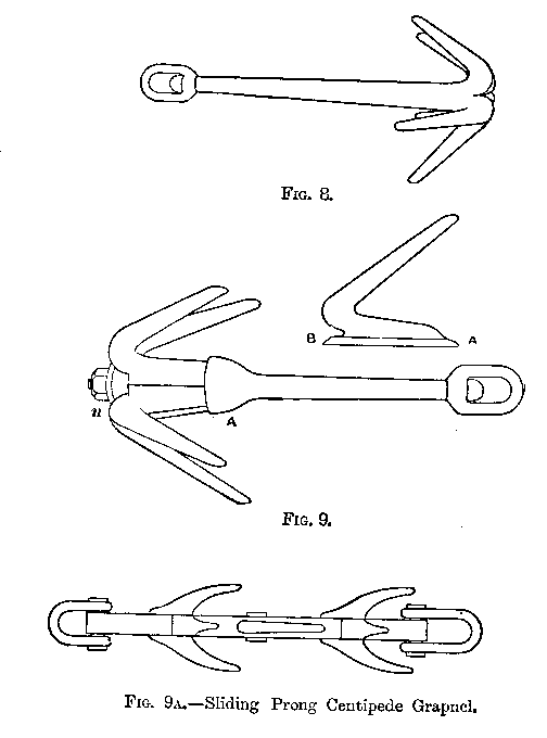
old form of 5 or 6-prong grapnel (Fig. 8) is still a very effectual
grapnel for bottoms of a soft nature, such as sand or ooze; but
meeting with any hard obstruction, such as rock, the prongs
bend down or break off. To retain the use of the shank of the
grapnel while the prongs are bent or broken off, many forms of
grapnel with removable prongs have been devised. In one of
these (Fig. 9), made by the Telegraph Construction and Maintenance Co.,
the prongs fit into a hollow boss on the shank at A, and the ends at B
are all enclosed by a collar and firmly fixed in
position by the nut n. Another form, constructed by Messrs. Johnson
and Phillips, is the sliding prong grapnel, which is provided with
removable cast steel prongs of the kind shown in Fig. 9A.
By taking the shackle off one end, the broken prongs may be slipped
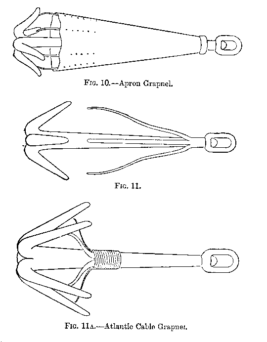
off and renewed. For rocky bottoms the Dutton apron grapnel
(Fig. 10) is frequently used. In this grapnel the apron forms a
guard for the prongs against breakage by rocks, and the opening
between the prongs and the lower edge of the apron is only a little
larger than required for the cable to enter. There are
also retaining springs from the apron to the prongs. The
grapnel in Fig. 11 has a guard for the same purpose,
made of four wrought-iron arms. These guards prevent
the cable getting out of the grapnel when it is jumping
over uneven ground. The first form of this kind of grapnel
was used in the "Great Eastern" when grappling for the lost
end of the '65 Atlantic cable. This was made by lashing five
bent steel springs, about 1+1/4in. wide by 3/16in. thick, to the stem
of the grapnel, as shown (Fig 11. 11A). It will be remembered
that the "Great Eastern" commanded by Capt. (afterwards Sir James)
Anderson, laid the '65 Atlantic cable from Ireland towards
Newfoundland, and that when about 1,180 miles from
Valentia an electrical fault developed in the cable. In attempting
to pick up and remove this fault the cable parted, the end
going overboard in 1,950 fathoms. This occurred on August 2nd
of that year, and all attempts then made to recover it
were ineffectual. But the "Great Eastern" returned in the
following year, and, after successfully laying the '66 cable,
went back to the position where the end of the former cable had
been lost, and eventually raised the end, with the grapnel described,
on September 2nd, completing the cable to Newfoundland
in six days from that date. This was the first occasion
on which a cable had been raised from a depth exceeding 500 fathoms.
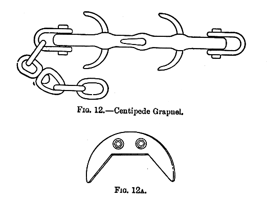
The centipede grapnel is shown in Fig. 12. One form of this
grapnel with renewable prongs is Cole's centipede. The prongs
are of cast steel, two prongs being in one casting of the shape
shown in Fig. 12A, and bolted to the shank of the grapnel.
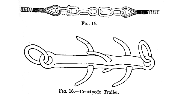
Trailers (as in Fig. 16) are used sometimes with the grapnels,
being dragged either after or before the grapnel, to keep it
from jumping, and at the same time offer a better chance of
hooking the cable. There is generally also a trailing or steering
chain attached to the end of the grapnel. This is a fathom or two
in length, and has at one end a large link, so as to
allow the other end to be reeved through it after being reeved through
the end link of the grapnel. The noose is then hauled
tight, and the chain follows the grapnel, and keeps it moving in
a straight line.
The forward end of the grapnel has usually about 15 fathoms
of 7/8in. chain attached to it to keep the front end low
as it is dragged along. To the end of this chain is shackled
the grapnel rope, which is usually a manilla rope, 6+1/2in. circumference,
with a breaking strain of about 11 tons. A length
of a few hundred fathoms of compound grapnel rope made of
six cable strands of hemp yarns, with three steel wires in each,
known as six-by-three rope, is generally shackled on between
the chain and manilla to bear the chafing against the bottom;
and this rope, for some distance near the chain, is covered with
old matting, pieces of yarn or old rope, lashed on to it in order
to form a series of raised places in the rope, which will drag
along the bottom, and prevent the rope from grazing along it,
and so wearing away. This precaution is only necessary in
very uneven grounds, as the chain in front of the grapnel is
supposed to take all the chafe. It is a common practice, however, to
put matting, &c., round the rope where it rests on the bow sheaves
to prefent chafing against the cheeks of the sheaves.
This is chiefly done when taking long drives in deep
water. This six-by-three rope alluded to is used by some ships
for the entire length, in place of manilla. The ends of each
length of grapnel rope have thimbles and links, and one end
always has a swivel and link in addition; and in coupling two
lengths of rope together, one end with the swivel and link is
used, and the shackle put through the two end links, as shown
in Fig. 15. If, then, the grapnel rolls over on the bottom
while grappling it cannot twist and cause kinks in the rope, as
the swivels between each length allow the rope to turn bodily.
4. Special Grapnels.
When working in great depths the
strain on the deep-sea type of cable is frequently the cause of
its parting. To obviate this, grapnels have been devised which,
simultaneously with hooking the cable, will cut it and hold the desired end.
This, of course, entails grappling again, unless near a total break,
but it is a more certain way to go to work, and
time-saving in the long run. When grappling for one end of a
total break in deep water, if the cable is hooked too far from
the break the strain my cause it to part afresh at the grapnel,
or if hooked too near the break the
end may slip through the grapnel in heaving
up and be lost. A grapnel of this kind,
therefore, which will
cut the cable at the moment it is hooked,
and abandon the short end
while holding and bringing up the other, is of special service
in operations where total breaks have to be repaired.
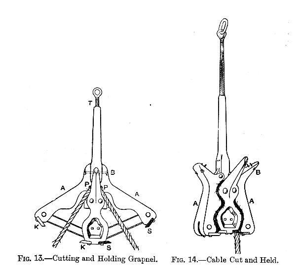
One of these forms of cutting and holding grapnel,
designed by Mr. F. R. Lucas, of the Telegraph Construction and
Maintenance Company, is shown in Fig. 13. Two arms A A,
pivoted on the pins P P, are held extended by two bolts, one
of which is shown at B in the figure. These bolts are thinned
down at the centre in the manner shown. The further ends of
the arms carry pulleys, round which a steel wire rope passes
as shown, the ends of the rope passing upwards through the
shank of the grapnel, where they are lashed together and form
the thimble at T by which the grapnel is hauled. There
are two prongs, one each side of the grapnel, and one of which
is shown in the figure. On hooking the cable, the strain on the
steel rope at T causes the extremities of the arms A A to bear
inwards with a force which causes the bolts at B to snap off at
the thin central part. The moment the bolts snap the full
force of the strain is brought to bear in clowsing the jaws,
and the bight of the cable is jammed in between the curved
portions of the arms and the central stem, as shown in Fig. 14.
As the jaws close, one pair of cutting edges, as at K K, close
across the cable on one side, and the rapidity and force of
closing cuts the cable clean through, leaving the other end firmly
gripped in the jaws. The pair of knife edges shown at
K K are on the near side, and would cut the left-hand side of
a cable hooked on the near prong, as shown in the figure.
The pair of edges S S are on the far side, and would only cut a cable
caught by the far prong.
In grappling it is, of course, only the lower prong that hooks the cable, and
supposing we are looking down upon this grapnel as it is being hauled along,
the underneath prong will hook the cable, and the pair of
edges S S will cut the cable on the right-hand side, as the pair of
edges K K are now on that side. So long, therefore,
as the grapnel is hauled in one direction with reference to
the line of cable, it will always cut the cable on the side
desired, no matter whether it rolls over or not, and will bring
up the right end. But if the direction of grappling is reversed,
the knives must be unbolted and shifted to the opposite side. This grapnel,
which has proved very successful, was used for the first
time on board the "Scotia" during the repairs of the Lisbon-Madeira cable,
in January, 1891, which it cut and brought up from a depth of 1,500 fathoms.
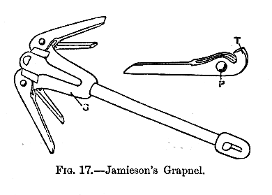
Jamieson's grapnel (Fig. 17) is designed to prevent breakage
of the prongs through coming in contact with rocks.
For this purpose the prongs are mounted on pins as at P,
about which the prong is capable of movement. The
inner end of the prong has a tongue as at T, which bears upwards
against a volute spring contained in the enlarged part of the shank at S.
When strained against rocks, therefore, the prongs give outwards, and as
soon as the obstacle is passed the internal spring acts on the tongue and
restores the prong to its position again. When the cable is hooked
the prongs do not give way, because the cable lays opposite the pivot of
the pront, or so close to it that no leverage is exerted.
Trott and Kingsford's automatic indicating grapnel is designed to give
notice by completing the circuit of an electric bell or indicator on board
immediately the the cable is hooked.
Mr H. Kingsford described this grapnel in an interesting Paper before the
Society of Telegraph Engineers and Electricians in November 1883. The weight
of the cable, as it lays in the grapnel, causes a brass piston or plunger at
the root of the prong to be pressed down, and an electrical contact made at
the grapnel, which completes the indicator circuit
through an insulated conductor in the heart of the grapnel
rope. The plungers are pointed below, and when weighted by the pressure
of the cable force their way through a rubber disc on to a brass
contact plate.
The grapnel rope containing the electrical core for use with this grapnel
is patented by Messrs. Trott and Hamilton, and, as no swivels are used,
the rope is specially designed with a view to the prevention of kinking
consequent upon the grapnel turning over on the bottom and twisting it.
The system, which is worked with the Anderson and Kennelly patent indicator,
has been used by Captain S. Trott and Mr. H. Kingsford on board the "Minia,"
the Anglo-American Company's repairing steamer, since the year 1883,
with great success.
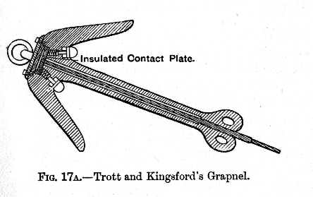
The illustration (Fig. 17A) shows the position of the
contact buttons and insulated plate in this grapnel; and it may be mentioned
here that should a prong become fractured or broken off, the insulation of
the contact plate will be partially destroyed, and a current set up which
can be distinguished on boardd, as it is weaker than that caused by hooking
cables. Notwithstanding the great ingenuity of this grapnel, there is
the disadvantage of requiring a special grapnel rope both on account of
the core and the fact that no swivels can be used, and it is not possible
with this rope to have it made up in sections of convenient lengths,
nor to use a
length of chain in front of the grapnel to bear the chafing on the bottom.
The devices described above for easily and quickly replacing the broken
prongs of a centipede grapnel by new ones have served the purpose of
limiting the very large number of complete grapnels that, otherwise,
a ship would be bound to carry, and have also effected a very considerable
saving in time. There is still, however, something left to be desired.
When a prong is broken off the grapnel generally tows with the broken
side underneath, and misses the cable, while it cannot be known on board
every time this occurs. And whether there has been a desire or not to put
to to frequent test the facility with which prongs on this or that system
can be renewed it is impossible to say, but the metal is very much skimped
in some specimens. Again, if prongs break easily, it may happen that one
on which the cable is safely lodged may break before the grapnel, owing
to slack of rope, has had time to lift, with the
result that the cable is lost. With the view of lessening these
defects as far as possible, Mr. Edward Stallibrass has devised and
patented the grapnel illustrated in Fig. 17B, which is
manufactured by Messrs. Muirhead and Co., of Westminster, London. Normally
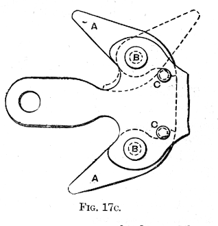
the toes A A in this grapnel are retained in position by the pins at C
(Fig 17C), but if, through meeting

with some obstruction while towing, a strain equal to three
tons is brought to bear on the point of a toe, the pin is sheared
through and the toe capsizes, turning on its pivot B to the
position indicated by the dotted lines. By this action a toe
can never get broken, and further, when in the capsized position it
projects more than before, which has the effect of canting the grapnel
over so that another toe takes the ground.
By varying the size of the
pin the toe can be made to capsize at any desired strain. The toe is
only used to guide the cable into a large rounded surface in the shank
of the grapnel, and consequently, although a toe might be capsized by a
rock after hooking the cable, the latter would not be lost. The
grapnel is made in two parts, each having four toes, and these
are shackled together, as in the illustration, or with a short
length of chain intervening. This enables it to fit better into
any irregularities of the ground, and increases the chances of
hooking a cable, besides being more convenient in other ways.
For soft bottoms longer toes are provided, and one single grapnel can
be used instead of the pair.


