|  GEOS SDK TechDocs|
  |
|  1.1 Chapter Structure |
  2 Graphics Goals
Several terms will crop up again and again in your dealings with graphics. Many of these terms will be familiar to programmers experienced with other graphics systems, but those not familiar with any of these terms are encouraged to find out what they mean.
-
GState, Graphics State
-
The graphics system maintains data structures called Graphics States, or GStates for short. GStates keep track of how a geode wants to draw things: the colors to use, current text font, scaling information, and so on. Most graphics routines, including all routines that actually draw anything, take a GState as one of their arguments. Thus to draw the outline of a red rectangle, you would first call the
GrSetLineColor()
routine to change the color used for drawing lines and outlines to red. Only after thus changing the GState would you call the
GrDrawRect()
command.
-
Standard Coordinate Space, Document Coordinate Space
-
Drawing commands in GEOS use the standard coordinate space, also known as the document coordinate space. This is a rectangular grid used for expressing locations and distances. This grid uses units of 1/72nd of an inch. Thus, drawing a point to (72, 72) will draw the point one inch to the right and one inch below the top left corner of an ordinary Content or document.
-
GString, Graphics String, Metafile
-
GString is short for Graphics String. A GString is a data structure representing a sequence of graphics commands. Graphics Strings are used many places in the system. GStrings are used to pass graphics through the clipboard. They serve as the descriptors of graphical monikers, which are in turn used as application icons. The printing system uses GStrings to describe images to be printed.
A graphics Metafile is just a file containing a GString, taking advantage of this data structure to store a graphics image to disk.
-
Bitmap
-
A bitmap is a picture defined as a rectangular array of color values. Note that since display devices normally have their display area defined as a rectangular grid for which each pixel can have a different color value, it is relatively easy to draw a bitmap to the screen, and in fact the graphics system normally works by constructing a bitmap of what is to be displayed and displaying it. Bitmaps are sometimes known as "raster images."
-
Path
-
Paths provide a precise way to specify arbitrary areas of the display area. Like GStrings, they are described by a sequence of drawing commands. Instead of defining a picture, these commands describe a route across the graphics space. The enclosed area can be used in a variety of operations.
-
Region
-
Regions provide another approach to describing arbitrary display areas. Regions use a compressed scan-line data structure to represent a pixel-based shape on the display. Though lacking the mathematical precision of paths, region-based operations are very fast and thus ideally suited to certain simple tasks.
-
Palette, RGB Values
-
Many display devices can display a wide variety of colors. Of these, most cannot display all their colors at once. Typical configurations can show 16 or 256 colors at a time out of a possible 256K. A palette is one of these subsets of the set of possible colors. When drawing something in color, normally the color to draw with is specified by the palette index, that color's place in the table.
The value stored in each entry is an RGB value, a color described in terms of its red, green, and blue components. Each of these three values ranges between 0 and 255. Geodes can change the RGB values associated with palette entries and thus change the available colors.
-
Video Driver
-
These geodes stand between the graphics system and the actual display device. They maintain device independence and do a lot of the "behind the scenes" work of the graphics system.
-
Windowing, clipping, "marked invalid"
-
The windowing and graphics systems are heavily intertwined. The graphics system controls how windows should be drawn, while the windows system keeps track of which parts of various displays are visible. For the most part graphics programmers don't have to worry too much about the windowing system, but there are some terms worth knowing.
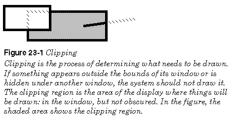
Clipping
is the process of keeping track of what things drawn to a window are actually visible. If a geode draws something beyond the edge of a window, the system can't just ignore the drawing, as the user might later reveal the drawing by scrolling onto that area. The graphics system "clips" the graphic, being sure to show only those parts that are in the visible part of a window. Further clipping takes place when a window is obscured behind another window. Any drawing on the lower window must not show up until the upper window is moved. The "clipping region" is that area of a window which is visible--anything drawn to the window outside the region will be clipped (see the figure below). Programs can reduce the clipping areas of any of their associated windows.
The windowing system is able to work much more quickly by assuming that not too many things are going to be changing at once. Normally it can assume that a given area of the screen will look like it did a short while ago. When it's time to change an area of the screen, that area is said to be "marked invalid," since whatever is presently being shown there is no longer valid. The normal example is that if a pull-down menu has been obscuring part of a document, when the menu goes away, the part of the document that becomes visible must be redrawn.
-
MSG_VIS_DRAW, MSG_META_EXPOSED -
These messages are sent to visible objects to instruct them to redraw themselves; if you are using graphics to display a visible object then you are probably intercepting MSG_VIS_DRAW. MSG_META_EXPOSED lets an object know that it has been marked invalid; either it has to be drawn for the first time, or part or all of it has been exposed (hence the name). The UI controller sends this message to the top object in the Vis hierarchy. MSG_VIS_DRAW, on the other hand, specifically instructs an object to redraw itself. Generally, a Vis object will respond to MSG_META_EXPOSED by sending MSG_VIS_DRAW to itself; it responds to MSG_VIS_DRAW by issuing the appropriate drawing commands, then sending MSG_VIS_DRAW to each of its children.
-
Graphic Objects
-
Graphic Objects provide the user with an interface for working with graphics in a manner similar to GeoDraw's. They are useful for programs which allow the users to construct some sort of graphical document or provide a sort of graphical overlay for a spreadsheet.
| GEOS SDK TechDocs|
| 1.1 Chapter Structure | 2 Graphics Goals